Description Of Function
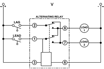
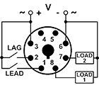
In the off state, both the LEAD Switch and the LAG Switch are open, the Alternating Relay is in the LOAD 1 position, and both LOAD 1 & LOAD 2 are off. The red LED marked "LOAD 1" is ON. When the LEAD Switch closes, it energizes LOAD 1. As long as the LEAD Switch remains closed, LOAD 1 remains energized. If the LAG Switch closes, it energizes LOAD 2. When the LAG Switch opens, LOAD 2 is turned off. When the LEAD Switch opens, LOAD 1 is turned off and the Alternating Relay toggles to the LOAD 2 position. The red LED marked "LOAD 2" is ON. When the LEAD Switch closes, it turns on LOAD 2. If the LAG Switch closes, it will energize LOAD 1. When the LAG Switch opens, LOAD 1 is turned off. When the LEAD Switch opens, LOAD 2 is turned off, the Alternating Relay toggles back to the LOAD 1 position, the red LED marked "LOAD 1" is ON, and the process can be repeated. NOTE: the LEAD switch must always close before the LAG switch and must always open after the LAG switch.
Function Chart

Application Information
- Voltage Tolerance: AC Operation: +10/-15% of nominal at 50/60 Hz.; DC Operation (12 & 24V only): +10/-15% of nominal.
- Load (Burden): Less than 3 VA
- Indicator LEDs: Two LEDs marked LOAD 1 and LOAD 2
- Selector Switch: ALTERNATE, LOAD 1; LOAD 2
- Output Contacts: 10A @ 240V AC/24V DC, 1/2HP @ 120/240V AC (N.O.), 1/3HP @ 120/240V AC (N.C.)
- Life: Mechanical: 10,000,000 operations; Full Load: 100,000 operations
- Temperature: -28o to 65o C (-18o to 149o F)
-
Approvals:


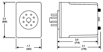
Dimensions - Inches (Millimeters)


