Using DPDT Cross-Wired Alternating Relays with HIGH-LOW Float Switches
Issue:
I have two float switches and two pumps in my application: a HIGH float switch to pump the water down and prevent an overflow of the tank, and a LOW float switch to turn the pump off and prevent the tank from being emptied & burning out the pump. I bought a DPDT Cross-Wired alternating relay to alternate the two pumps, thinking that I could make my HIGH & LOW float switches work where the LEAD & LAG switches are shown. But, I now find that is not possible. Is there anything I can do with the two float switches I have and the Macromatic alternating relay to work in my application?
Solution/Resolution:
Alternating Relays with DPDT cross-wired output configurations are typically used to control two loads when the need to have both loads on at the same time for additional capacity is required. When the LEAD Switch closes, it energizes LOAD 1. If the LAG Switch closes, it energizes LOAD 2. When the LAG Switch opens, LOAD 2 is turned off. When the LEAD Switch opens, LOAD 1 is turned off and the Alternating Relay toggles to the LOAD 2 position, ready to repeat the cycle again.
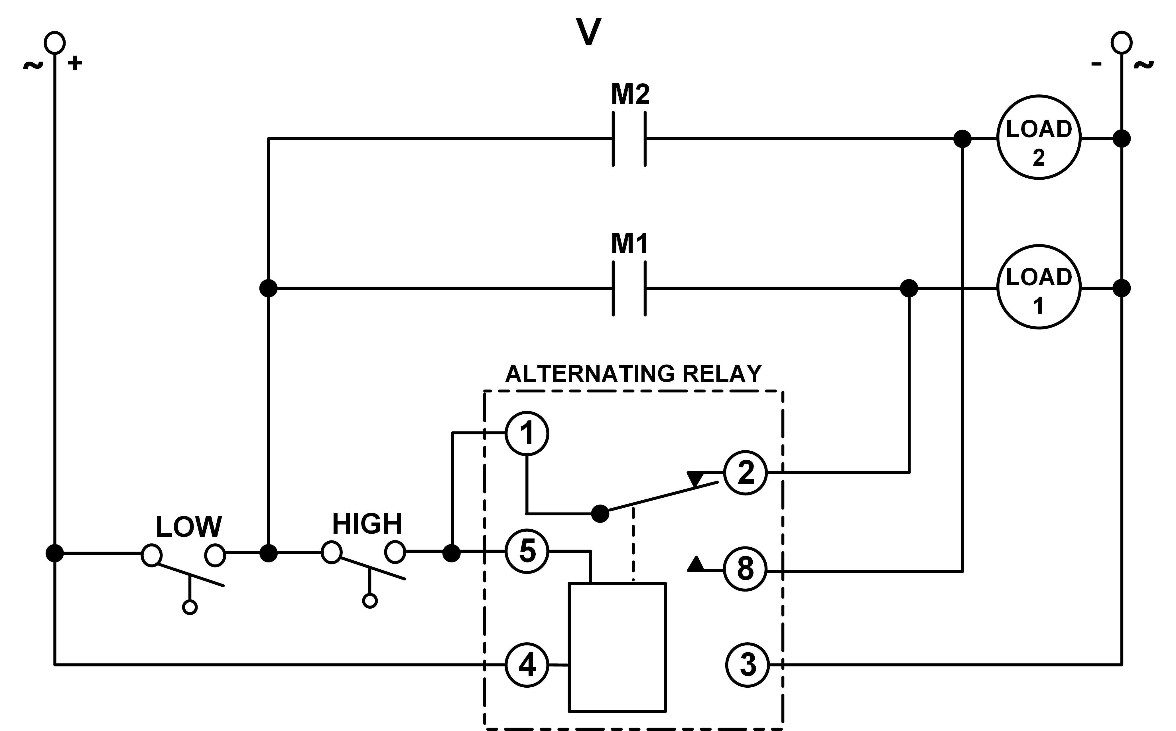
However, a LEAD & LAG switch is not the same as having a HIGH & LOW switch. The only way to make a DPDT Cross-Wired Alternating Relay work with a HIGH & LOW float switch is to utilize one auxiliary contact on each contactor and use the following connection diagram:

As the water rises, the LOW float switch is closed. As the water rises, it closes the HIGH float switch, turning on Pump #1. When the water begins to go down, the HIGH float switch opens, but Pump #1 remains on because auxiliary contact M1 is held closed. When the water gets low enough, the LOW float switch opens, turns off Pump #1 & opens auxiliary contact M1, and the alternating relay switches to the other position. The next time the water rises, the HIGH float switch will turn on Pump #2. NOTE: even though a Cross-Wired alternating relay is normally used with a LAG switch connected to Pin 2, it is not required in this application and nothing should be connected to Pin 2.
A similar connection diagram would apply to an application with both a HIGH & LOW switch but utilizing a SPDT Alternating Relay:
If you have any questions or need additional information, please contact Macromatic tech support at 800-238-7474.
Recent Articles for:
Alternating Relays
- Jun2020 Triplex Pump Control Using Cost-saving Alternating Relays
- Aug2019 What is Sequence On – Simultaneous Off (S.O.S.O. or SOSO) Operation on Pump Control?
- Aug2019 Typical Applications for Alternating Relays
- Nov2018 Using Alternating Relays with DC Input Voltages
- Jan2018 Using DPDT Cross-Wired Alternating Relays with HIGH-LOW Float Switches