Modification to Order a Product that is Normally an 8 Pin Product with 11 Pins (-H Suffix) No Longer Available
Issue:
In the past I have purchased a time delay relay with the H option, but it is now obsolete. What can I do?
Solution/Resolution:
We certainly apologize that this option is no longer available and therefore, may cause some inconvenience for you.
This option was to take a time delay relay that normally came with 8 pins & build it with 11 pins. This was done to replace another brand of product that came with this pin configuration:
 |
 |
| Standard 8 Pin Product i.e., TR-50222-04 |
Product with –H Modification i.e., TR-50222-04H |
Notice that both products use two terminals for input voltage and six pins for the DPDT relay output. However, the 11 pin version with –H modification has three empty terminals.
In 2011, we redesigned our TR-5 Series of products, the only product ever offered with the –H modification. During the process of analyzing options for the new design, we reviewed all modifications offered in the past. When we looked at the "-H" option, we found that we had only sold an average of 5 units per year. Therefore, we decided that continuing to offer this option was not economical and obsoleted it on the new TR-5 design.
If you have bought a TR-5 product with a “-H” option is the past, you have two alternatives:
Option #1
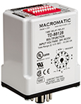
Purchase one of our digital-set multi-function time delay relays that come with 11 pins as standard (click on the Series for additional information):
| (Click on Series for More Information) | Input Voltage | Catalog Number | Wiring Diagram |
|---|---|---|---|
|
|
120VAC/DC | TD-88122 |  |
| 12VDC | TD-88126 | ||
| 24VAC/DC | TD-88128 | ||
| 240VAC | TD-88121 | ||
|
TD-7 Series
|
120VAC/DC | TD-78122 |  |
| 12VDC | TD-78126 | ||
| 24VAC/DC | TD-78128 | ||
| 240VAC | TD-78121 |
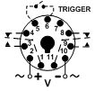
The wiring diagrams for the TD-8 & TD-7 products are shown above. Notice that with the exception of the trigger switch shown in dotted lines, the pin configuration is the same as shown above for a product with the -H modification. All the TR-5 products previously sold with a -H modification were either an On Delay or Interval On function, neither of which require a trigger switch. Therefore, if you purchase one of these units, set the function to either On Delay or Interval On by following the instructions provided with the product and wire it per the diagram above less the trigger connection. It will mount in the current 11 pin socket & operate the same as the unit you are replacing.
Option #2
Purchase a standard TR-5 product without the "-H" suffix along with our 8 pin socket (70169-D). For example, if you have previously purchased a TR-50222-04H from Macromatic with an 11 pin header, purchase a TR-50222-04 with 8 pins (no -H suffix) and the 70169-D 8 pin socket. You would then have to install & wire the 8 pin socket in place of the 11 pin socket as shown below:
 |
 |
| Product with -H Modification | Standard 8 Pin Product |
Differences in Socket Wiring
- Input Voltage: The 11 pin -H socket has input voltage connected to pins 2 &10. The input voltage would have to be connected to pins 2 & 7 on the 8 pin socket (watch polarity if using dc).
- Output: one SPDT relay output is connected to pins 1-3-4 on both the 11 pin & 8 pin socket, with pin 1 the relay common. However, the second SPDT relay output on the 11 pin socket is connected to pins 11-9-8, with pin 11 the relay common. It would have to be reconnected to pins 8-6-5 on the 8 pin socket, with pin 8 the relay common.
If you have questions, please feel free to contact our technical support group at 800-238-7474 or e-mail tech-help@macromatic.com.


