What is a True Off Delay Timer?
Issue:
What is the difference between an "Off Delay" & a "True Off Delay" time delay relay, and when is the True Off Delay function used?
Solution/Resolution:
Pneumatic time delay relays worked great, but they were normally very large & very expensive. In addition, they were only available in two functions: On Delay with Normally Open Timed Closed (N.O.T.C.) & Normally Closed Time Open (N.C.T.O.) contacts; and Off Delay with Normally Open Timed Open (N.O.T.O.) & Normally Closed Time Closed (N.C.T.C.) contacts.
Sometime in the seventies, manufacturers developed solid state time delay relays, originally using some type of RC (resistor-capacitor) circuit to set the time delay. Most now use either IC's or microprocessors for function & time delay.
One of the downsides of solid state time delay relays was trying to replace Off Delay pneumatic units. The older pneumatic units did not require input voltage to be maintained during the Off Delay period: when input voltage was applied to a pneumatic Off Delay unit, the contacts changed state-when the voltage was removed, the contacts remained in their changed state until the air had passed from one chamber to the other, thus completing the time delay & changing the contacts back to their normal state.
On the other hand, solid state Off Delay products require continuous input voltage to ensure that both the logic circuit & output relay had power to keep them energized during the Off Delay period. Otherwise, when input voltage is removed, the relay will drop out immediately instead of completing the OFF delay period.
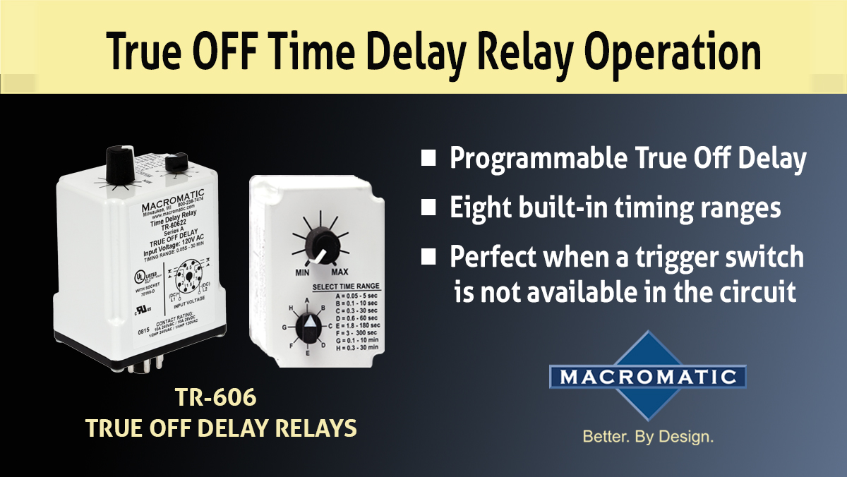
Operation of Off Delay Function
Upon application of input voltage, the time delay relay is ready to accept a trigger. When the trigger is applied, the output is energized. Upon removal of the trigger, the time delay (t) begins. At the end of the time delay (t), the output is de-energized. Any application of the trigger during the time delay will reset the time delay (t) and the output remains energized.
To solve this problem, manufacturers came up with what is commonly called a "True Off Delay" unit. In these products, the logic circuit & relay are kept energized by an on-board power source. This could be a capacitor that discharges during the off delay period to keep the logic & output relay energized. Or it could be a latching relay that remains latched closed during the off delay period, then is unlatched by a small capacitor that discharges during the Off Delay period. Another option is to have a small battery. In all cases, the idea is to for the unit to have its own power supply for the off delay period vs. an external power supply as in standard off delay solid-state units.
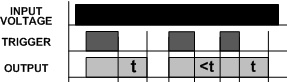
Operation of True Off Delay Function
Upon application of input voltage, the output is energized. When the input voltage is removed, the time delay (t) begins. At the end of the time delay (t), the output is de-energized. Input voltage must be applied for a minimum of 0.1 seconds to assure proper operation. Any application of the input voltage during the time delay (t) will reset the time delay. No external trigger is required.
There is also a version called an On Delay/True Off Delay. Here is how it works:
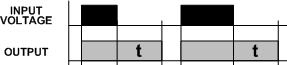
Operation of On Delay/True Off Delay Function
Upon application of input voltage, the time delay (t1) begins. At the end of the time delay (t1), the output is energized. When the input voltage is removed, the output remains energized for the time delay (t2). At the end of the time delay (t2), the output is de-energized. Input voltage must be applied for a minimum of 0.1 seconds to assure proper operation. Any application of the input voltage during the time delay (t2) will keep the output energized & reset the time delay (t2). No external trigger is required.
Therefore, for applications replacing older pneumatic time delay relays or where input voltage is not available during the off delay period, the true off delay function is perfect.
For more information, please contact Macromatic Technical Support at 800-238-7474.