Trouble-Shooting Tips for Plug-In Products
We frequently receive technical support calls from installers that can't get their plug-in product to function correctly. This is understandable because unless you work with plug-in products on a regular basis; there are several idiosyncrasies to these products that are not common knowledge. The Trouble-Shooting tips below cover the most common issues we see and will help you get your Macromatic Plug-In device operating as intended.
Check for proper pin to socket terminal number orientation.
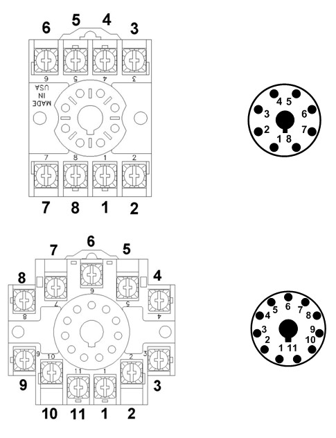
The industry standard method for illustrating a plug-in product wiring diagram is to show the perspective of looking at the bottom of the plug-in product as if you were holding the device in your hand with the pins pointing up. This can cause confusion because the pin orientation of the wiring diagram is opposite the terminal numbering orientation of the socket. In other words, the wiring diagram shows the mirror image of how the device actually plugs into the socket. To ensure proper wiring, always reference the pin number to the terminal number on the socket. See the illustration below which shows that terminals on the right side of the socket are on the left side of the wiring diagram.

Be sure to connect the desired voltage source to the common contact of the relay output.
The relay outputs of most plug-in products are isolated from the input voltage of the unit. This is done to provide the flexibility of switching a different voltage than the input voltage. For example your plug-in timer uses 120 VAC input voltage and you want to switch 12 VDC with the relay outputs. This is made possible with isolated relay contacts. This also means that you must connect the voltage source to the common relay contacts; otherwise you will not have a relay output. For more information on this issue, visit Knowledge Base Article Input Voltage Applied But Nothing Coming Out!!
Verify correct input voltage polarity on DC applications.
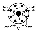
Macromatic plug in products designed to operate with DC input voltage are polarity dependent. If the polarity is incorrect the device will not operate correctly. The wiring diagram on the label of the product indicates proper polarity. See example below showing DC (+) on pin 2 and DC (-) on pin 7. For more information on this issue, visit Knowledge Base Article DC Input Voltages on Time Delay Relays.

Plug-in time delay relays with triggered functions require a Dry Contact Control Switch
Several time delay functions such as OFF-DELAY, SINGLE-SHOT, WATCHDOG or TRIGGERED DELAYED INTERVAL require a control switch to trigger the function. This circuit requires a dry contact switch (no voltage) such as a pushbutton or toggle switch. Applying voltage to the control switch will prevent proper operation and will most likely damage the timer. Ensure that the control switch circuit is a dry contact only. If your application requires a control switch with voltage, Macromatic offers Power Trigger time delay relay options. For more information on this issue, visit Knowledge Base Article Troubleshooting a Unit with a Control Switch Trigger.
