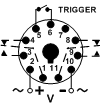
Troubleshooting a Unit with a Control Switch Trigger
Issue:
I am using one of your products that has the control switch trigger between Pins 5 & 6, and the unit is not operating. What could possibly be wrong?
Solution/Resolution:
Normally when we receive this question, the problem is traced to a blown resistor in the control switch trigger circuit. Most of the time this resistor has been blown open because voltage was inadvertently applied to either pins 5 or 6. Remember, a control switch trigger is a dry contact switch, meaning no voltage is required. Applying voltage to either pin will damage the unit and cause it to become inoperative.
If you need to trigger a time delay relay such as off delay, single shot or watchdog with voltage instead of a dry contact switch, Macromatic offers a power trigger version of these functions on our TR-5 & TR-6 Series time delay relays (not available on TD-7 Series Digital-Set or SS-8 Compact time delay relays). Notice the difference in the wiring diagrams below. Diagram 1 is a control switch trigger unit, where all that is required is any type of switch to open & close across pins 5 & 6. Diagram 2 shows a power trigger switch product, where the application of voltage to pins 5 & 7 will initiate the timing function.
|
|
 |
|
Diagram 1 |
Diagram 2 |
A couple of points to keep in mind regarding power trigger units. First, notice that the polarity of the power trigger voltage connected to pins 5 & 7 must match the polarity of the input voltage connected to pins 2 & 10. Second, one advantage of power trigger products is that they can be controlled from a much greater remote distance than control switch trigger units (contact Macromatic for more information). And finally, for special applications, Macromatic can offer time delay relays with special trigger switch voltages that are different than the input voltage, i.e., if the input voltage is 120V but the application requires a power trigger switch voltage of 5vdc from a PLC or other output. Contact Macromatic for additional information).

