Circuit Design for Intrinsic Safety
Intrinsic Safety Overview
When installing electrical equipment in or near hazardous area locations, specific circuit design principles must be followed in order to prevent an explosion. Depending on the region of the world, and the application requirements, different techniques or concepts are followed. In Europe, Intrinsic Safety is widely used. Circuit design in North America more commonly follows explosion proof techniques. But that is changing as the benefits of Intrinsic Safety become more widely understood.
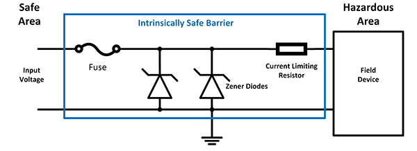
Intrinsic Safety is based on the principle of preventing low-voltage circuits in a hazardous areas from releasing enough energy to cause an explosion. This is typically accomplished using a protective circuit known as an intrinsically safe barrier. In normal operation, and in the event of a fault, the Intrinsically Safe Barrier protects the field circuit by preventing excess energy from reaching the hazardous area.
There are three main components in the barrier that limit the voltage and current: a resistor, at least two Zener Diodes, and a fuse. The resistor limits the current to a specific value known as the short circuit current, Isc. The Zener Diode limits the voltage to a value referred to as open circuit voltage, Voc. The fuse will open when the Zener Diode conducts thereby further protecting the circuit.
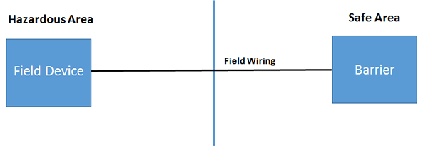
When considering the Intrinsically Safe Circuit in a control system, there are three main components: 1) The field device (can be either a simple or non-simple device), 2) The field wiring, 3) The barrier.
A simple field device will neither generate nor store more than 1.2V, 0.1A or 25mW. Therefore, the simple device is connected to the Intrinsically Safe Barrier through the field wiring. Examples of simple devices are contacts, thermocouples and RTD’s.
If the field device does create or store energy that exceeds 1.2V, 0.1A or 25mW, then it is considered a non-simple device. Examples of non-simple devices are transmitters, transducers, solenoid valves and relays. Non-simple devices must be certified as intrinsically safe and connected to an approved Intrinsically Safe Barrier. When designing the intrinsically safe circuit with non-simple devices, it is important to compare the entity values (electrical parameters which describe the contribution or burden that a given device will add to an intrinsically safe circuit) of the non-simple device against the entity values of the barrier.
The Macromatic ISD & ISE Series of Intrinsically Safe Relays provide a safe, reliable and cost-effective method to control multiple loads (motor starters, relays, etc.) with multiple input devices (switches, sensors, etc.) which are in a hazardous area.
Learn More: Hazardous Location Classification
Recent Articles for:
Intrinsically Safe Barrier Relays