Understanding Entity Parameters
Designing Intrinsically Safe Circuits
When designing Intrinsically Safe Circuits, it is imperative to understand the entity parameters of the devices in your circuit. The entity parameters describe characteristics of the device, as well as what can safely be connected to it. As discussed in Intrinsic Safety Overview, the three components of an Intrinsically Safe Circuit are the field device, field wiring, and the barrier.
Field devices can be broken into two types, simple and non-simple devices. Simple devices are defined as devices that do not generate or store more than 1.2V potential, 100mA current, 20uJ energy, and 25mW power. Simple devices do not have entity parameters.
Non-simple devices must be certified as intrinsically safe for use in hazardous areas; a certified non-simple device is referred to as an Intrinsically Safe Apparatus. These devices will be marked with, or have accompanying documentation, providing entity parameters that govern their safe use as a field device within an intrinsically safe circuit.
Entity Parameters can be broken into two different categories, Associated Apparatus (devices that are installed in the safe area and interface between Hazardous Location and the safe location) and Intrinsically Safe Apparatus (non-simple devices that are installed in the Hazardous Location).
Entity Parameters for Associated Apparatus
| Uo/Voc | Maximum voltage passed into Hazardous Location |
| Io/Isc | Maximum current passed into Hazardous Location |
| Po | Maximum power passed into Hazardous Location |
| Co/Ca | Maximum capacitance that can be connect to device |
| Lo/La | Maximum inductance that can be connected to device |
Entity Parameters for Intrinsically Safe Apparatus
| Ui/Vmax | Maximum voltage that can be connected to device |
| Ii/Imax | Maximum current that can be connected to device |
| Pi | Maximum power that can be connected to device |
| Ci | Maximum internal capacitance of the device |
| Li | Maximum internal inductance of the device |
When designing an Intrinsically Safe circuit (field device, field wiring, and barrier) each of the following must be true.
Vmax ≥ Voc
Imax ≥ Isc
Ci + Ccable ≤ Ca
Li + Lcable ≤ La
Most of these values above can be gathered from documentation provided with the barrier and field device used. The capacitance (Ccable) and inductance (Lcable) of cable must be calculated using the two following equations. The inductance and capacitance values per foot used below are the default “worst case” parameters established for use when actual properties of the wire/cable are not known. Actual wire/cable properties can be substituted in place of these when available.
Lcable = 0.2uH/foot * feet of cable
Ccable = 60pF/foot * feet of cable
Design Example
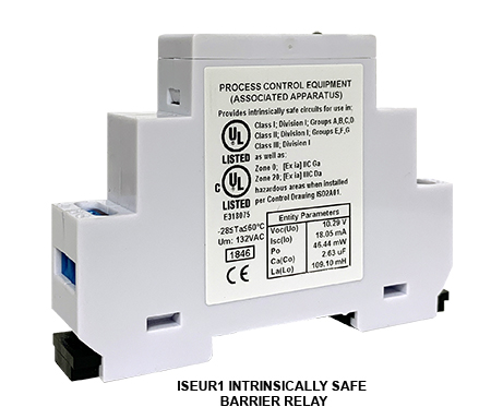
In this example, the Macromatic ISEUR1 Intrinsically Safe Barrier Relay is the “barrier” used to interface with the hazardous area. The associated apparatus entity parameters for the ISEUR1 are listed below.
Voc = 10.29V
Isc = 18.05mA
Ca= 2.63uF
La= 109.1mH
The ISEUR1 will be connected to a “field device” in the hazardous area. In this example, the field device is an Intrinsically Safe Apparatus and must meet the following requirements, based on the barrier entity parameters of the barrier, to maintain intrinsic safety.
Vmax ≥ 10.29V
Imax ≥ 18.05mA
Ci + Ccable ≤ 2.63uF
Li + Lcable ≤ 109.1mH
Assuming the Intrinsically Safe Apparatus that has the following Entity parameters:
Vmax = 15V
Imax = 30mA
Ci = 2uF
Li = 2mH
- Vmax of 15V is greater than 10.29V required, this meets the requirement.
- Imax of 30mA is greater than 18.05mA, this meets the requirement.
In order to verify the capacitance and inductance parameters, the capacitance and inductance of the interconnecting wire/cable must be calculated. For this example, we will assume a 500 foot long wiring run for 1000 total feet of cable.
Lcable = 0.2uH/foot * 1000 = 0.20mH
Ccable = 60pF/foot * 1000 = 0.060 uF
- Ci + Ccable = 2.06uF, this is less than the 2.63uF limit and meets the requirement.
- Li + Lcable = 2.2mH, this is less than the 109.1mH limit and meets the requirement.
The barrier, field device, and field wiring as described would be allowable based on entity parameters.
Calculating Maximum Wire/Cable Length
Sometimes the barrier and field device are known, but wire/cable length is not. In this situation, it can be more helpful to know the maximum length of wire/cable that would be allowable.
The allowable cable length can be calculated as follows:
Cable Length ≤ (Co-Ci)/(0.2uF/Foot) = (109.1mH-2mH)/(0.2uH/Foot) = 535,500 Ft
Cable Length ≤ (Lo-Li)/(60pF/Foot) = (2.63uF-2uF)/(60pF/Foot ) = 10,050 Ft
The maximum length of cable allowable is 10,050 feet, the lesser of the two values.
(Note: this is total length, the sum of the length of both supply and return conductors.)
The Macromatic ISD & ISE Series of Intrinsically Safe Barrier Relays provide a safe, reliable and cost-effective method to control loads (motor starters, relays, etc.) with input devices (switches, sensors, etc.) located in a hazardous area.
Learn More: An Overview of Hazardous Location Classification
Recent Articles for:
Intrinsically Safe Barrier Relays