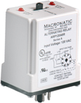
ARP Duplex Controllers
Plug-in
| Features |
|
| Enclosure Style | Plug-in case utilizing industry-standard 8 pin octal sockets |
| Configuration/ Contact Rating |
|
| Approvals |    UL File #E109466 UL File #E109466 |
| Technical Documentation |
|
With Switch |
Top-Mounted Switch |
Operation:

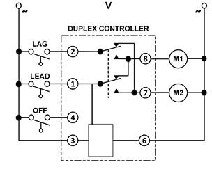
In the initial OFF state, all three switches are open, the Duplex Pump Controller is in the LOAD 1 position, and both loads are off (see Diagram right). No action happens with the Controller or either load when the OFF switch closes. When the LEAD Switch closes, LOAD 1 turns on. When the LAG Switch closes, LOAD 2 turns on. Both loads remain on as long as all three switches are closed.
When the LAG Switch opens, LOAD 2 remains on because the Duplex Controller simulates the function of an auxiliary contact. When the LEAD Switch opens, LOAD 1 remains on for the same reason. When the OFF Switch opens, both LOAD 1 and LOAD 2 are turned off simultaneously because all voltage is removed to both loads. The Duplex Controller toggles to the LOAD 2 position. The entire cycle is then repeated, but with LOAD 2 energized first followed by LOAD 1.
These products protect against failure of the OFF or LEAD Switches—if one or both of these switches fail to close in sequence, the two LOADS will be energized when the LAG switch closes. In addition, both LOADS are turned off simultaneously when the LAG switch opens.
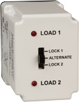
These products have a three position selector switch. This provides the option to alternate the two loads as normal or select which load always comes on first when the LEAD switch closes. In either case, a load that has fewer hours of operation than the other load could be used more often to eventually balance the run time of both loads. The low-profile selector switch prevents any accidental changes in status.


