Time Delay Relays
Encapsulated
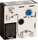
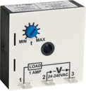
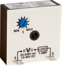
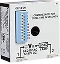
THx Series Time Delay Relays utilize a microprocessor-based design for greater performance and maximum flexibility. All products are encapsulated for protection against harsh environments. Choose between adjustable or fixed onboard or remote time delay.
Three output configurations, all in a 2" x 2" package, are offered to fit most applications:
| THR-1 Series Relay Output |
THS-1 Series Solid State Output |
THL-1 Series Solid State Output Inline (Series-Connection) |
THL-8 Series Solid State Output Inline (Series-Connection) | THR-3 Series Programmable Relay Output |
|
 |
 |
 |
 |
 |
|
| Output | 10A SPDT Relay | 1A Normally Open Solid State | 1A Normally Open Solid State | 1A Normally Open Solid State | 10A SPDT Relay |
| Functions Available |
|
|
|
|
Each Catalog Number has 3 Functions built-in: THR-3816U:
THR-3836U:
THR-3856U:
|
| Input Voltages | 12V DC, 24V AC/DC, 120V AC/DC, 240V AC | 24-240V AC or 12-125V DC | 24-240V AC & 12-48V DC Universal Voltage | 24-240V AC & 12-48V DC Universal Voltage | 24-240V AC & 12-125V DC Universal Voltage |
| Timing Ranges | 8 Ranges Covering 0.05 Second - 100 Hours Adjustable or Fixed--Onboard or Remote |
9 Ranges Covering 0.01 Second - 100 Hours Adjustable or Fixed--Onboard or Remote |
9 Ranges Covering 0.01 Second - 100 Hours Adjustable or Fixed--Onboard or Remote |
3 Ranges Covering 0.1 Sec -10,230 Seconds | 4 Ranges Covering 0.1 Second - 100 Minutes (1,000 Minutes on THR-3856U) Adjustable or Fixed--Onboard or Remote |
Issue:
What is the difference between On Delay, Off Delay, Single Shot, Interval On and all these other time delay functions?
Solution/Resolution:
Understanding the differences between all the functions available in time delay relays can sometimes be a daunting task. When designing circuits using time delay relays, questions such as what initiates a time delay relay, does the timing start with the application or release of voltage, when is the output relay energized, etc., must be asked.
Time delay relays are simply control relays with a time delay built in. Their purpose is to control an event based on time. The difference between relays and time delay relays is when the output contacts open & close: on a control relay, it happens when voltage is applied and removed from the coil; on time delay relays, the contacts can open or close before or after some time delay.
Typically, time delay relays are initiated or triggered by one of two methods:
- application of input voltage
- opening or closing of a trigger signal
These trigger signals can be one of two designs:
- a control switch (dry contact), i.e., limit switch, push button, float switch, etc.
- voltage (commonly known as a power trigger)
CAUTION: any time delay relay that is designed to be initiated with a dry contact control switch trigger could be damaged if voltage is applied to the trigger switch terminals. Only products that have a "power trigger" should be used with voltage as the trigger.
To help understand, some definitions are important:
- Input Voltage-control voltage applied to the input terminals. Depending on the function, input voltage will either initiate the unit or make it ready to initiate when a trigger is applied.
- Trigger Signal-on certain timing functions, a trigger is used to initiate the unit after input voltage has been applied. As noted above, this trigger can either be a control switch (dry contact switch) or a power trigger (voltage).
- Output (Load)-every time delay relay has an output (either mechanical relay or solid state) that will open & close to control the load. Note that the user must provide the voltage to power the load being switched by the output contacts of the time delay relay.
Below are both written and visual descriptions on how the common timing functions operate. A Timing Chart shows the relationship between Input Voltage, Trigger (if present) and Output. If you cannot find a product to fit your requirements or have any questions, Macromatic's Application Engineers offer technical information along with product selection and application assistance. Either e-mail or call us at 800-238-7474 for help.
NOTE: not all functions are available on any of our multi-function products. Please check the catalog pages or specification sheets of each multi-function product to confirm what functions are included.
| Function | Operation | Timing Chart |
| ON DELAY Delay on Make Delay on Operate |
Upon application of input voltage, the time delay (t) begins. At the end of the time delay (t), the output is energized. Input voltage must be removed to reset the time delay relay & de-energize the output. | 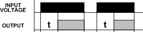 |
| INTERVAL ON Interval |
Upon application of input voltage, the output is energized and the time delay (t) begins. At the end of the time delay (t), the output is de-energized. Input voltage must be removed to reset the time delay relay. | 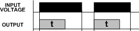 |
| OFF DELAY Delay on Release Delay on Break Delay on De-Energization |
Upon application of input voltage, the time delay relay is ready to accept a trigger. When the trigger is applied, the output is energized. Upon removal of the trigger, the time delay (t) begins. At the end of the time delay (t), the output is de-energized. Any application of the trigger during the time delay will reset the time delay (t) and the output remains energized. | 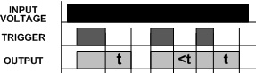 |
| SINGLE SHOT One Shot Momentary Interval |
Upon application of input voltage, the time delay relay is ready to accept a trigger. When the trigger is applied, the output is energized and the time delay (t) begins. During the time delay (t), the trigger is ignored. At the end of the time delay (t), the output is de-energized and the time delay relay is ready to accept another trigger. | 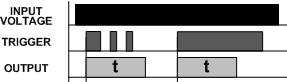 |
| FLASHER (Off First) |
Upon application of input voltage, the time delay (t) begins. At the end of the time delay (t), the output is energized and remains in that condition for the time delay (t). At the end of the time delay (t), the output is de-energized and the sequence repeats until input voltage is removed. | 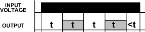 |
| FLASHER (On First) |
Upon application of input voltage, the output is energized and the time delay (t) begins. At the end of the time delay (t), the output is de-energized and remains in that condition for the time delay (t). At the end of the time delay (t), the output is energized and the sequence repeats until input voltage is removed. | 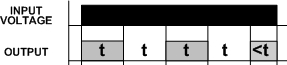 |
| ON/OFF DELAY | Upon application of input voltage, the time delay relay is ready to accept a trigger. When the trigger is applied, the time delay (t1) begins. At the end of the time delay (t1), the output is energized. When the trigger is removed, the output contacts remain energized for the time delay (t2). At the end of the time delay (t2), the output is de-energized & the time delay relay is ready to accept another trigger. If the trigger is removed during time delay period (t1), the output will remain de-energized and time delay (t1) will reset. If the trigger is re-applied during time delay period (t2), the output will remain energized and the time delay (t2) will reset. | 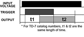 |
| SINGLE SHOT FALLING EDGE | Upon application of input voltage, the time delay relay is ready to accept a trigger. When the trigger is applied, the output remains de-energized. Upon removal of the trigger, the output is energized and the time delay (t) begins. At the end of the time delay (t), the output is de-energized unless the trigger is removed and re-applied prior to time out (before time delay (t) elapses). Continuous cycling of the trigger at a rate faster than the time delay (t) will cause the output to remain energized indefinitely. | 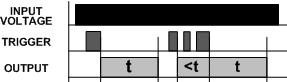 |
| WATCHDOG Retriggerable Single Shot |
Upon application of input voltage, the time delay relay is ready to accept a trigger. When the trigger is applied, the output is energized and the time delay (t) begins. At the end of the time delay (t), the output is de-energized unless the trigger is removed and re-applied prior to time out (before time delay (t) elapses). Continuous cycling of the trigger at a rate faster than the time delay (t) will cause the output to remain energized indefinitely. | 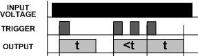 |
| TRIGGERED ON DELAY | Upon application of input voltage, the time delay relay is ready to accept a trigger. When the trigger is applied, the time delay (t) begins. At the end of the time delay (t), the output is energized and remains in that condition as long as either the trigger is applied or the input voltage remains. If the trigger is removed during the time delay (t), the output remains de-energized & the time delay (t) is reset. | 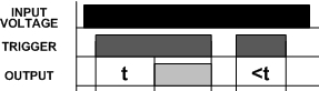 |
| REPEAT CYCLE (OFF 1st) |
Upon application of input voltage, the time delay (t1) begins. At the end of the time delay (t1), the output is energized and remains in that condition for the time delay (t2). At the end of this time delay, the output is de-energized and the sequence repeats until input voltage is removed. | 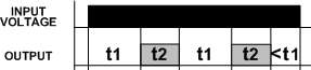 |
| REPEAT CYCLE (ON 1st) |
Upon application of input voltage, the output is energized and the time delay (t1) begins. At the end of the time delay (t1), the output is de-energized and remains in that condition for the time delay (t2). At the end of this time delay, the output is energized and the sequence repeats until input voltage is removed. | 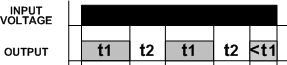 |
| DELAYED INTERVAL Single Cycle |
Upon application of input voltage, the time delay (t1) begins. At the end of the time delay (t1), the output is energized and remains in that condition for the time delay (t2). At the end of this time delay (t2), the output is de-energized. Input voltage must be removed to reset the time delay relay. | 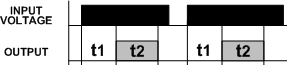 |
| TRIGGERED DELAYED INTERVAL Single Cycle |
Upon application of input voltage, the time delay relay is ready to accept a trigger. When the trigger is applied, the time delay (t1) begins. At the end of the time delay (t1), the output is energized and remains in that condition for the time delay (t2). At the end of the time delay (t2), the output is de-energized & the relay is ready to accept another trigger. During both time delay (t1) & time delay (t2), the trigger is ignored. | 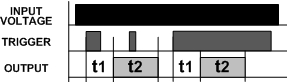 |
| TRUE OFF DELAY | Upon application of input voltage, the output is energized. When the input voltage is removed, the time delay (t) begins. At the end of the time delay (t), the output is de-energized. Input voltage must be applied for a minimum of 0.5 seconds to assure proper operation. Any application of the input voltage during the time delay (t) will reset the time delay. No external trigger is required. | 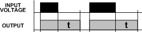 |
| ON DELAY/ TRUE OFF DELAY | Upon application of input voltage, the time delay (t1) begins. At the end of the time delay (t1), the output is energized. When the input voltage is removed, the output remains energized for the time delay (t2). At the end of the time delay (t2), the output is de-energized. Input voltage must be applied for a minimum of 0.5 seconds to assure proper operation. Any application of the input voltage during the time delay (t2) will keep the output energized & reset the time delay (t2). No external trigger is required. | 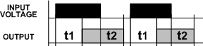 |
| SINGLE SHOT-FLASHER | Upon application of input voltage, the time delay relay is ready to accept a trigger. When the trigger is applied, the time delay (t1) begins and the output is energized for the time delay (t2). At the end of this time delay (t2), the output is de-energized and remains in that condition for the time delay (t2). At the end of the time delay (t2), the output is energized and the sequence repeats until time delay (t1) is completed. During the time delay (t1), the trigger is ignored. | 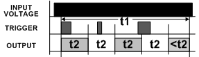 |
| ON DELAY-FLASHER | Upon application of input voltage, the time delay begins (t1). At the end of the time delay (t1), the output is energized and remains in that condition for the time delay (t2). At the end of this time delay (t2), the output is de-energized and remains in that condition for the time delay (t2). At the end of the time delay (t2), the output is energized and the sequence repeats until input voltage is removed. | 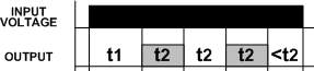 |
| PERCENTAGE | Upon initial application of input voltage, the output is energized and time delay (t1) begins. Time Delay (t1) is adjustable as a percentage of the overall cycle time (t2). At the end of time delay (t1), the output is de-energized for the remainder of overall cycle (t2-t1). The sequence then repeats until input voltage is removed. If input voltage is removed and reapplied, the timing cycle will continue from where it left off when the input voltage was removed. A setting of 100% energizes the output continuously while a setting of 0% de-energizes the output continuously. | 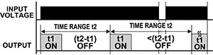 |
| PERCENTAGE (NO MEMORY) | Upon initial application of input voltage, the output is energized and time delay (t1) begins. Time Delay (t1) is adjustable as a percentage if the overall cycle time (t2). At the end of time delay (t1), the output is de-energized for the remainder of overall cycle (t2-t1). The sequence then repeats until input voltage is removed. If input voltage is removed and reapplied, the timing cycle will be reset. A setting of 100% energizes the output continuously while a setting of 0% de-energizes the output continuously. | 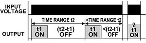 |
Macromatic's Time Delay Relays Knowledge Base contains general and technical industry articles to help you learn more about Time Delay Relays.
This process will assist you in selecting the correct product for your application. Just answer the following questions and we will lead you to the product best suited for your needs. Should you require additional assistance, contact Macromatic Technical Support at 800-238-7474. Click on the appropriate photo to learn more about the specific product
offerings:
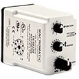

Plug-in
Encapsulated
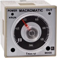
1/16 DIN
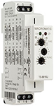
17.5mm Modular